Read this first
JINI is an architecture proposal with experimental mechanical models. Nothing on this page has been printed, fitted or worn. Every clearance quoted here is CAD against catalogue dimensions, and the ear it was drawn around is a published adult average, not a scan of yours.
Tested firmware. REJI's reji_client.ino will not drive this
wiring unchanged — see step 09.
A fit guarantee. Comfort, retention, flex durability, acoustics, runtime
and heat are all untested.
Permission to skip the bench. The transducer goes against the side of your
head. Prove it at low level on the bench first.
This supersedes the v3 documents
If you have the older JINI-assembly-v3/PRINT_THIS/ folder open, close it. That
is the right-ear v3 kit with eleven screws and eleven inserts. The current
parts are the left-ear v4 set in JINI-PRINT-ALL-10-PARTS/:
four screws, four inserts, and two of the covers reprinted in TPU so they hold by friction
instead of hardware.
| What changed | v3 right ear | v4 left ear |
|---|---|---|
| Ear | right | left |
| Screws / inserts | 11 / 11 | 4 / 4 |
| 03 ribbon cover | PETG, 3 screws | TPU, friction |
| 04 camera retainer | PETG, 2 screws | TPU, friction |
| Envelope | 89.3 × 82.8 × 25.6 mm | 93.9 × 82.6 × 25.9 mm |
| Plastic mass | 43.7 g | 37.96 g PETG + 4.81 g TPU |
| Transducer | assumed | confirmed Adafruit 1674 |
The electronics bill of materials, the wiring table and the power checks in
HARDWARE_AND_WIRING.md are unaffected by the v4 reshape and are reproduced
below. Its screw and insert counts are not.
The ten parts
Drag to turn it. Tap a part number to isolate it in the model — the same chips appear beside the steps that touch each part.
The exploded view shows removal directions, not installation order. Grey is PETG-HF, green is TPU 95A. Do not print the assembled reference models — print the ten STLs.
| # | Part | Material | Bed | H | Vol | Retention |
|---|---|---|---|---|---|---|
| 01 | Main frame | PETG-HF | 91.0 × 82.2 | 20.9 | 23.39 cm³ | Hollow rear shell, open cable channel, camera stalk, transducer housing. Carries all four inserts. |
| 02 | Rear lid | PETG-HF | 30.3 × 59.3 | 11.0 | 2.72 cm³ | 2 × M2 × 6. Its inner feet retain the deck. |
| 03 | Ribbon cover | TPU 95A | 65.9 × 31.9 | 7.0 | 1.57 cm³ | Friction. Peels off for access to the cable and crown coupler. |
| 04 | Camera retainer | TPU 95A | 17.4 × 17.4 | 3.8 | 0.35 cm³ | Friction. Pulls forward along the lens axis. |
| 05 | Contact cover | PETG-HF | 19.1 × 34.5 | 1.6 | 0.92 cm³ | 2 × M2 × 6. Holds the foam shim behind the transducer. |
| 06 | Electronics deck | PETG-HF | 21.3 × 46.4 | 2.2 | 1.52 cm³ | Rests on side ledges above the battery. Boards strapped to it. |
| 07 | Battery sled | PETG-HF | 21.6 × 42.0 | 6.4 | 1.11 cm³ | Slides out after lid and deck. Pull tab faces the lead bay. See step 02. |
| 08 | Contact boot | TPU 95A | 21.0 × 36.4 | 4.3 | 1.01 cm³ | Stretches over the skin-facing contact housing. Thin insulating membrane. |
| 09 | Rear cushion | TPU 95A | 24.0 × 50.0 | 1.6 | 0.79 cm³ | Thin removable double-sided tape, skin side of the rear shell. |
| 10 | Battery port plug | TPU 95A | 4.8 × 9.4 | 6.5 | 0.23 cm³ | Friction dust cover over the JST disconnect. Not a seal. |
All ten files are closed single solids, one body each. Largest axis 91 mm; everything
fits a 180 mm bed. Hashes in SHA256SUMS.txt.
Bill of materials
| Qty | Component | Notes |
|---|---|---|
| 1 | XIAO ESP32S3 Sense with expansion board and antenna | Reuse REJI's board if it is this version, camera removed. CAD allocation 17.8 × 23.2 × 8.5 including USB. No pin headers. |
| 1 | Seeed OV5640 + heat sink 114993115 | Confirmed. Allowance 8.7 × 8.7 × 5.7, native 6 mm flex. Keep the heat sink. |
| 1 | Adafruit 1674 bone-conduction transducer | 8 Ω, 1 W RMS / 2 W max, 14 × 21.5 × 8. Confirmed — JINI's pocket cross-section is identical to REJI's and 3.1 mm deeper. |
| 1 | Adafruit MAX98357A breakout 3006 | New part for this layout. 19.4 × 17.8 mm PCB, 8.5 mm height allowance including terminal block. Zero clearance on every face — caliper it. |
| 1 | Adafruit 2750 LiPo, 3.7 V / 350 mAh | Protected, JST-PH. Nominal 19.6 × 36 × 5.2; the manufacturer drawing says 20 ±0.3 × 36 ±1 × 5.6 ±0.2. See step 02. 525 mA max continuous discharge. |
| 1 | Adafruit 4524 FPC coupler | 24-pin, 0.5 mm. Lies flat in the crown pocket. Fits 0.3 mm cable ends. |
| 1 | 24-conductor 0.5 mm Type A FFC, 12.5 mm wide, 75 mm | Candidate extension, not a validated OV5640 accessory. 100 mm only if the slack routes gently. Do not buy 250 mm. |
| 1 | JST-PH 2-pin mating lead | Adafruit 3814 or equivalent. Insulated pigtail; the disconnect sits at the side access opening. |
| 1 | 100 kΩ resistor | MAX GAIN → VIN, minimum hardware gain. Insulate it. |
| 1 | 10 kΩ resistor | MAX SD → GND, so it stays shut down through MCU reset. |
| 1 | Adafruit Micro Lipo 1304 | External charger, set to 100 mA. Never its 500 mA setting for this cell. Charging happens off-body. |
| 4 buy 10 | M2 × 6 mm pan/button head | 0.4 mm pitch, measured under the head, head Ø ≤ 4 mm. No countersunk, no self-tappers. Rear lid 2, contact cover 2. |
| 4 buy 10 | ruthex RX-M2x4 heat-set inserts | 4 mm long, max outer Ø 3.6 mm. Other sizes need a matching CAD hole. |
Mechanically the breakout is 24 × 15 mm and the amp bay takes at most 22.0 × 15 mm, in either orientation. Electrically it is an analog amplifier and the ESP32-S3 has no DAC, so it would need a PDM + RC stage or a separate I2S DAC board that does not fit. No DAC, boost converter, charger board, microSD card or second transducer goes inside this shell.
Tools and consumables
- Calipers — step 01 is entirely calipers, and two components have no margin at all.
- Multimeter — battery polarity, continuity on the camera extension, shorts before power.
- Current-limited bench supply at 3.7 V — first power-on happens here, not on the cell.
- Temperature-controlled soldering iron with an M2 heat-set insert tip.
- Small driver, flush cutters, deburring tool, tweezers.
- Wire: ~0.5 m each red/black 28 AWG stranded, OD ≤ 1 mm · ~0.3 m per signal colour of 30 AWG, OD ≤ 0.7 mm · ~0.4 m total of two 30 AWG speaker wires, lightly twisted.
- Kapton tape, thin insulation film, heat-shrink; thin removable double-sided tape for the rear cushion.
- Nonconductive soft foam, roughly 0.5–3 mm, for camera and transducer anti-rattle shims. Never against the LiPo.
Caliper the components
Before any plastic is committed. Two components in this design have no room to be anything other than nominal, and one of them is already known to be a problem.
Every direction. The envelope grazes the plenum wall at two points — the amplifier's +Y/+Z corner and the battery disconnect touch the same rib. A nominal board drops in. Anything over nominal, including a terminal block taller than 8.5 mm or solder tails on the underside, will not. Check which revision Adafruit shipped you.
Measured growth room, per face
Millimetres before the part touches rigid PETG. > means nothing rigid within 3 mm on that side.
| Component | Modeled as | −X | +X | −Y | +Y | −Z | +Z |
|---|---|---|---|---|---|---|---|
| Adafruit 2750 LiPo | 19.6 × 36.0 × 5.2 | 0.20 | 0.20 | 0.20 | 0.60 | 0.50 | 0.10 |
| XIAO ESP32S3 Sense | 17.8 × 23.2 × 8.5 | 1.47 | 1.47 | 0.42 | > | 0.60 | 0.20 |
| MAX98357A 3006 | 19.4 × 17.8 × 8.5 | 0.00 | 0.00 | 0.00 | 0.00 | 0.00 | 0.00 |
| OV5640 + heat sink | 5.7 × 8.7 × 8.7 | 0.40 | > | 0.30 | 0.30 | 0.30 | 0.30 |
| Transducer (1674) | 14.0 × 21.5 × 8.0 | 0.34 | 0.34 | 0.34 | 0.34 | 2.80 | > |
| 4524 FPC coupler | 10.5 × 2.2 × 18.5 | 0.35 | 0.35 | 0.35 | 0.35 | > | 0.35 |
The camera and the XIAO have workable margin. The camera's +X side is open because the TPU retainer, not a rigid wall, closes it.
JINI's trans_pocket cross-section is 14.7 × 22.2 mm — identical to REJI's, and 3.1 mm deeper, with the extra room on the outward side. A transducer that seats in REJI seats here. Fit is settled; coupling is not, because JINI puts a TPU membrane between the transducer face and skin and REJI did not.
Do not sand electronics, bend a heat sink, crush a pouch or force a connector to make a number work. Account for solder and insulation.
Fix the battery bay
The sled's inner walls sit at x = ±10.0, so the free bay is 20.00 (W) × 36.8 (L) × 5.80 (T) mm. The Adafruit 2750's actual manufacturer drawing — PKCELL LP552035, linked from Adafruit's own product page — gives 20 ±0.3 mm wide and 5.6 ±0.2 mm thick. Thickness clears. Width does not: a nominal cell is exactly 20.0 mm in a 20.00 mm bay, and roughly half of the cells off the line land on the plus side of that tolerance.
Thickness holds at 5.80 for any width up to 20.00 and collapses beyond it, so width is the only binding axis. This is not specific to the 2750 — any 20 mm-class pouch has it, including the P502030 in the parts bin.
Pick one before printing part 07
- Measure your actual cell. If it comes in at 19.8 mm or under, print as released and move on — but measure the one you will install, not a sibling.
- Thin the sled walls from 0.8 mm to about 0.5 mm, putting the inner face at ±10.3 for a 20.6 mm bay. Reprints part 07 only: 1.11 cm³, and the sled is a non-structural tray. Cheapest real fix.
- Replace the side walls with short end tabs, removing the constraint entirely. Also part 07 only.
- Widen the frame's pod cavity too. Correct, but it reprints part 01 — 23 cm³ and the long pole of the whole print.
There is only 0.2 mm to give before the sled fouls the frame: the sled's outer wall sits at ±10.8 and the frame's pod cavity at ±11.0. That is why options 2 and 3 exist rather than simply moving the wall outward.
The drawing marks the JST PH-2P on this cell as a reversed plug. Verify polarity with a meter regardless of lead colour. 1S PCM protection (S-8261AAJMD + 8814), 525 mA maximum continuous discharge.
Print the fit coupons
The coupons in JINI-assembly-v3/PRINT_THIS/00_FIT_COUPONS_PETG-HF/ are v3 files,
but every component envelope and the 3.2 mm insert diameter are unchanged between v3 and v4.
They are a few grams in total.
| Coupon | Tests | Print it? |
|---|---|---|
| E | Insert pilots, 3.0 / 3.2 / 3.4 mm | Yes — minimum. The insert process is the one thing you cannot fix after the fact. |
| A | OV5640 module and heat sink pocket | Recommended. |
| C | Rear battery compartment (the lower shell, not the sled) | Recommended, especially alongside step 02. |
| F | XIAO footprint clearance, 19 × 24 | Coarse footprint gauge only — verify the complete XIAO and amplifier height with calipers too. |
| B | Rectangular transducer pocket | Optional. The 1674 is confirmed against REJI's identical pocket; print it only for reassurance in hand. |
| D | Coupler and ribbon | Skip. It tests crown geometry that v4 reshaped. |
Dial in the insert process on coupon E before you put a hot tip anywhere near part 01.
Print the ten parts
From JINI-PRINT-ALL-10-PARTS/. One of each. Nothing else in that folder is a
printable part, the material is in every filename, and no G-code, supports or printer
profile is embedded — select your own profile.
Slicing
- Layer height 0.12–0.16 mm. Walls are 1.4–2.0 mm and the insert bosses are M2. Coarse layers will not hold the bosses.
- Do not re-orient. Every file already sits on Z = 0 in its intended orientation. Seam and layer direction matter on the hook and the thin covers — ask before changing one to save support material.
- Do not scale anything. Scaling breaks every fastener and component fit.
- 01_main_frame is the critical part. Curved hook, blind cable channel, four insert bosses. Supports are needed under the hook overhang and the camera stalk. Use tree/organic supports if available and keep them out of the cable channel on the inside of the hook.
- 05, 06 and 09 are thin at 1.6–2.2 mm. Print flat, as oriented.
- TPU 95A at 20–25 mm/s, no or minimal supports, direct-drive extruder. 03_ribbon_cover is the one TPU part with real geometry and it must stay flexible enough to peel off — do not over-extrude it.
Insert bosses in part 01 are 3.2 mm diameter × 5 mm deep. Expect about 38 g of PETG-HF and 5 g of TPU by solid volume, before infill savings, supports and purge.
Deburr and dry-fit
Remove accessible supports and deburr every edge. Then, with no electronics involved:
- Check the camera pocket accepts the module from the front.
- Check the board USB lines up with the bottom opening.
- Check the microphone vent is clear.
- Check connector access through the side opening.
- Place every cover loosely, without screws, and confirm nothing rocks.
- Pass the two speaker wires through the stalk now, before any electronics go in. They are far harder to thread later.
This is a left-ear part drawn around a 63 × 35 mm published adult average. Ear shape and contact pressure have not been measured. Hold the inert frame in place and find out now whether the geometry is wrong, not after it has a battery in it.
Install four inserts
All four RX-M2x4 inserts go into part 01: four blind bosses, 3.2 mm diameter × 5 mm deep. Two serve the rear lid, two serve the contact cover. Parts 03 and 04 are TPU friction covers in v4 and take no hardware at all.
- Use the process you proved on coupon E.
- Set them flush, square and slowly with a suitable heat-set tip.
- Let each one cool fully before testing it with a screw.
- Do this before any camera, cable, transducer or battery goes in.
Every screw is M2 × 6 mm measured under the head. Pilot depth is 5 mm. Hand-tighten only until seated. Do not reach for a longer screw. If a cover rocks or needs force to close, find the interference instead of tightening it down.
Bench-wire the electronics
On the bench, out of the enclosure. Battery and USB disconnected while soldering. Solder thin flexible wires directly — no vertical pin headers. Insulate exposed joints, both board undersides and the two resistors.
Never the physical pad position in an online photograph.
| From | To | Purpose |
|---|---|---|
| Battery connector + | XIAO BAT+ and MAX VIN | 3.0–4.2 V battery rail |
| Battery connector − | XIAO BAT− / GND and MAX GND | Common power ground |
| XIAO D1 / GPIO2 | MAX BCLK | I2S bit clock |
| XIAO D3 / GPIO4 | MAX LRC | I2S word clock |
| XIAO D6 / GPIO43 | MAX DIN | I2S audio data — reserve this pad, do not also use UART TX |
| XIAO D4 / GPIO5 | MAX SD | LOW = mute/shutdown, HIGH = enabled, left channel |
| MAX SD | 10 kΩ → GND | Reset-state mute |
| MAX GAIN | 100 kΩ → VIN | 3 dB hardware gain; power-cycle after changing |
| MAX SPK+ | Transducer lead A | Differential speaker output |
| MAX SPK− | Transducer lead B | Never connect either speaker lead to GND |
| Sense camera socket | 75 mm Type A FFC → 4524 coupler → native OV5640 flex | Camera connection — see step 08 |
| Supplied antenna plug | XIAO antenna connector | Antenna tapes to the exterior plastic lid, active area clear of battery and metal |
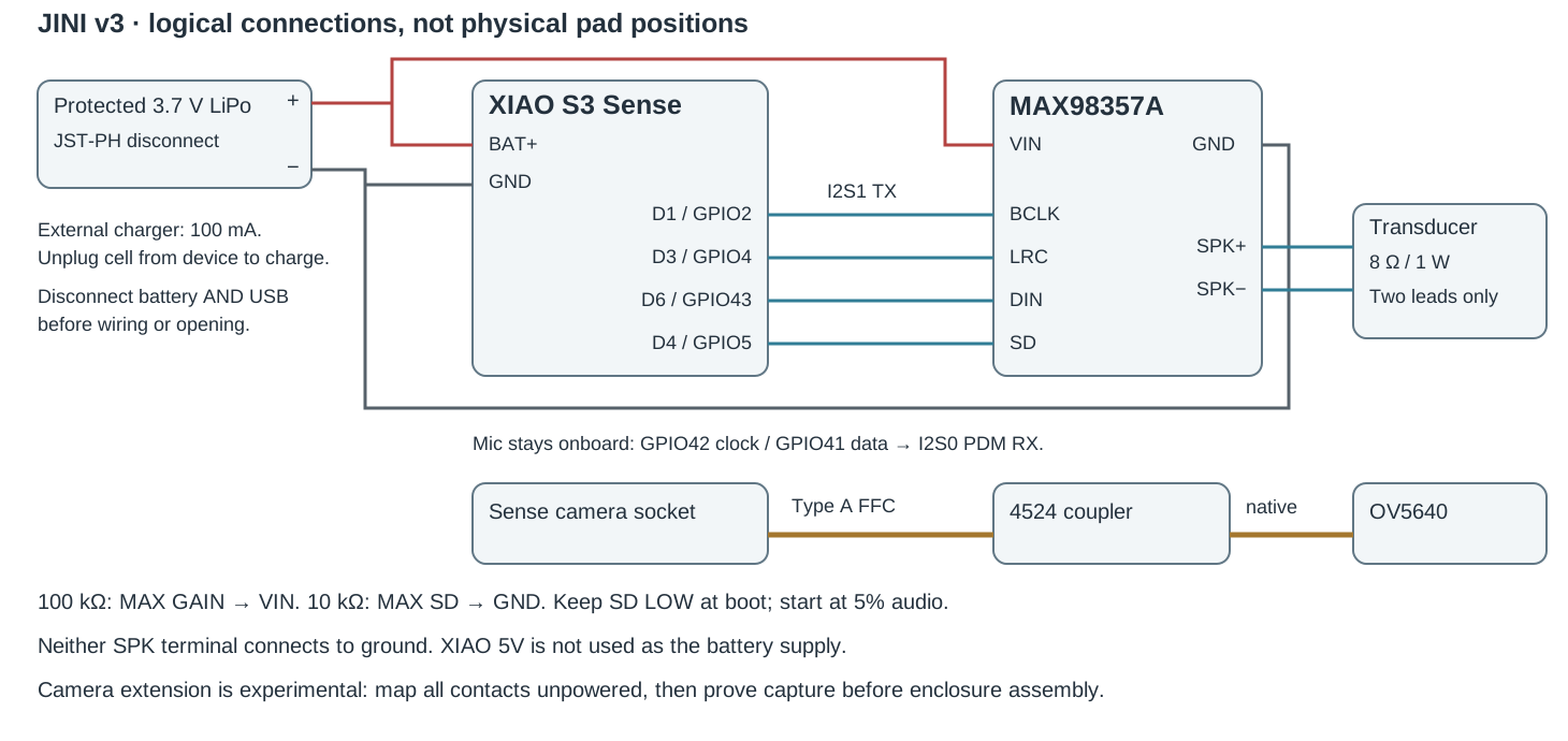
Rules that are easy to get wrong
- The built-in Sense microphone stays on GPIO42 clock / GPIO41 data. It needs no added wiring.
- Do not wire the amplifier to XIAO's 5V pad. That pad is not a 5 V battery output.
- The MAX98357A needs no external MCLK.
- The battery connector is the hard power disconnect. Its device-side positive lead branches to BAT+ and amplifier VIN — insulate each branch separately.
- The onboard charger can energise the BAT rail from USB even with no battery fitted. For a hard power-off or any wiring work, disconnect both USB and battery.
- Never connect the external charger and the device to the battery at the same time.
- Leave enough slack to lift the deck, but do not bundle spare wire above the boards where the lid closes. Start with long pigtails, dry-lay, then trim and record the actual cut lengths.
Camera cable gate
The 4524 supplier states that pin 1 at one side connects to pin 24 at the other and calls for Type A cable. That is not proof that any given 24-pin cable has the correct end-to-end mapping for your camera. This is a parallel camera bus, not a guaranteed cable-length upgrade.
With everything unpowered:
- Identify pin 1 and the contact face on the actual Sense socket and on the camera flex.
- Map the coupler and extension conductor by conductor, using a breakout or accessible contacts. Do not force meter tips into a ZIF socket.
- Confirm every camera signal reaches the same board signal as in the original direct connection. Check adjacent conductors for shorts. Record the orientation.
- Establish capture with the camera directly attached, then repeat through the extension, using Seeed's XIAO Sense camera example with OV5640-compatible settings. Start at QVGA, then test the resolution and frame rate you actually intend to use.
- Gently arrange the cable into the intended hook curve while capturing. If images drop, corrupt or fail to initialise, stop and revise the interconnect.
The CAD reserves about 43 mm along the front hook including a turn allowance, against a conservative 58 mm usable native camera tail. That is a length check — not a validated flex bend, twist or signal-integrity result.
While you are on the bench: prove the microphone and the standard-I2S amplifier path with low-level audio, and check the whole power load against the cell's limits.
Firmware allocation
REJI/firmware/xiao_esp32s3/reji_client.ino defaults to PDM TX on I2S1.
Espressif lists PDM TX on both ports but states the PCM-to-PDM converter is on
I2S0 only — and REJI's microphone already owns I2S0 for PDM RX. That path
would need software PCM-to-PDM conversion, not a driver config change. It is moot here
anyway: the MAX98357A takes standard Philips I2S on I2S1 with no converter, no RC filter
and no DAC. Keep the original REJI code unchanged until you have a separate tested
JINI client.
Implement and bench-verify
- Microphone: I2S0, PDM RX, GPIO42/41, 16 kHz, signed PCM16.
- Amplifier: I2S1, standard Philips I2S TX — GPIO2 BCLK, GPIO4 WS, GPIO43 DOUT, 16 kHz, 16-bit stereo slots. Duplicate mono into both slots.
- GPIO5 drives SD. Set LOW before initialising audio; hold it low after any driver failure. Enable only for playback, and mute after DMA has drained. Check every driver install, pin and write return value.
- Start at 5% of full scale in software, with the specified 3 dB hardware gain. Increase only on the bench, watching transducer power, current and acoustics.
- Keep the backend PCM rate consistent with 16 kHz, or configure both ends together.
- Do not run a UART TX peripheral on GPIO43.
Camera capture support, shared-assistant integration and simultaneous camera/audio operation are still software work. This kit implements none of it.
Fit the camera
Disconnect all power before this point.
- Lay the native OV5640 flex along the front portion of the open hook.
- Feed its small tail through the rear camera opening while seating the heat-sink module into the square pocket from the front. The lens points through part 04.
- Keep the flex's connector stiffener straight and make the rear turn gently. The actual flex may want a different service loop than the CAD length allowance.
- Place the coupler flat in the widened crown pocket. It must not be bent to follow the curved hook.
- Join native flex to coupler, then run the measured Type A extension from the coupler down the rear hook to the Sense socket. Use the orientation you recorded in step 08 and latch both ends.
- Keep the FFC's broad face following the channel, with its width across the hook.
- Strain-relieve with small Kapton tabs on insulated flex, away from the latches. Tape must never pull on a ZIF.
- Press part 04 home. If needed, add a thin nonconductive anti-rattle shim around the heat sink's back or perimeter.
Do not cover the lens, pull the flex taut, or fully wrap the heat sink in foam. Confirm an unobstructed camera image before closing the ribbon cover. The calculated optical check uses a 69° field and a 4.9 mm entrance aperture — the actual image is the final vignetting test.
Part 03 overlaps the 4524 coupler envelope by 32 mm³ — the soft crown cap sits 1.4 mm into the coupler's 10.5 × 2.2 footprint, and a further 13 mm³ into the amplifier. In TPU 95A a small preload would be intentional retention, but 1.4 mm is a lot of squeeze against a rigid FPC connector body. Expect one of two outcomes on the first build: the cap deforms and holds the coupler down, which is fine, or it will not seat flush and puts standing load on the connector, which is not. Seat the crown cap by hand and check the coupler's latch still closes freely. Part 03 is 1.57 cm³ — cheap to trim or reprint.
Fit the transducer
- Slip part 08 over the skin-facing side of the contact housing. Its skirt has slight intentional interference; the membrane separates the contact face from skin. Tape only the skirt if it needs extra retention.
- Feed the two fine speaker wires through the stalk and open hook (threaded in step 05), leaving a small slack loop at the transducer's lead exit. Keep them beside the camera flex, not crossing screw seats or pressing on latches.
- Load the transducer from the outward/open side, contact face toward the TPU membrane, leads toward the stalk. Nominally its front sits about 0.1 mm behind the membrane and its back about 3.3 mm below the cover.
- Trim a soft foam pad behind it so the cover stops rattling without clamping the moving or coil parts. The exact shim depends on your measured transducer.
- Fit part 05 with two M2 × 6 screws.
REJI screwed its cover down over a bare transducer. JINI puts a TPU membrane and a foam shim in the path, and both can affect bone-conduction coupling. Bench-test intelligibility at low level and adjust before the device goes near your head.
Battery and deck
Battery
- Put the protected 350 mAh pouch flat into part 07, lead end toward the upper connector bay.
- Add only thin insulating tape where needed. Do not pack foam over it and do not use the lid to compress it.
- Place the sled on the rear shell floor. The battery sits below the deck; no screw passes through its space.
Boards
- Place the XIAO on the lower portion of part 06, USB pointing toward the bottom opening.
- Place the MAX98357A on the upper portion.
- Retain both with removable Kapton straps through the deck's side slots, clear of the microphone, connectors and hot components.
- Keep wire joints inside the stated board allocation and verify lid clearance.
- Do not cover the onboard microphone with tape. The side vent opens into its rear chamber; there is no modeled acoustic tube aligned to a measured capsule.
Leads and antenna
- Route battery wires around the deck's upper-side notch. The mated JST pair has a 15 × 8 × 5 mm allowance in the upper lead bay.
- Keep it loose enough to withdraw through the left-side opening for disconnecting. Check this with your actual lead before fitting part 10 — do not plan on yanking the battery's factory wires.
- Set the deck on the two shell ledges; its corner notches clear the insert posts.
- Connect the tested camera extension to the Sense socket, correct orientation.
- Connect the antenna gently and route its coax through the side exit. Tape the antenna to the outer plastic lid, active region clear of metal. The cavity is not sized for a particular antenna PCB. Secure the coax for strain relief.
Close the shell
- Lay every wire flat below all seating faces.
- Seat part 03 by hand — friction fit in v4, no screws. Confirm the coupler latch still closes freely underneath it.
- Fit part 02 with two M2 × 6 screws. Its feet hold the deck; the lid should seat without forcing boards or wiring down.
- Attach part 09 with thin removable tape on the skin side of the rear shell.
- Check that USB is accessible and the battery connector can still be disconnected through its opening.
- Fit part 10. It is a dust plug, not a waterproof seal.
Hand-tighten only. If either cover rocks or needs force, open it and find the interference rather than tightening it down.
Weigh, wear, power
Unpowered first
Weigh the assembled prototype and check its balance on an unpowered fit check. Computed solid-plastic mass is about 42.8 g before electronics and screws — substantially heavier than the appearance maquette this shape came from. Do not assume its comfort, retention, drop strength or skin-contact suitability from a render.
Then the bench supply, not the cell
Bring up on a current-limited 3.7 V supply at the battery input, with battery and USB disconnected. Verify there is no short before raising the current limit. Use one power source only for this test.
Then a short powered test, covers fitted
- Camera image.
- Microphone pickup.
- Quiet idle — no hiss, no pop on enable.
- Low-level audio through the transducer.
- Current draw and surface temperature.
- The battery disconnect, through its opening.
The cell's datasheet specifies 525 mA maximum continuous discharge. That is a limit, not a measured device draw. Check the whole device at low battery, on Wi-Fi transmit, during camera capture and at maximum allowed audio, and leave margin below it. An initial engineering target is ≤ 420 mA sustained. A cell-protection trip is not a current-regulation strategy — if the load cannot stay inside the battery's ratings, revise the cell and the enclosure before use. No runtime is promised.
Remove the device immediately if it becomes uncomfortable or hot. Charge the removable cell off-body at 100 mA, and inspect the pouch, leads and enclosure for pressure points before closing it again.
Taking it apart
- Disconnect battery and USB.
- Rear lid (02) lifts outward — two screws.
- Lift the deck (06) with its boards and slack wires still attached.
- Lift the battery sled (07).
- The rear lid must come off before the ribbon cover (03) can be lifted.
- Camera retainer (04) pulls forward along the lens axis.
- Contact cover (05) lifts outward — two screws.
Release the Kapton straps and unplug the flex connectors before moving connected components. The digital removal checks model rigid parts only — they do not model a soldered harness under tension.
Established: all files are closed single solids with consistent normals, no modeled rigid
part or component-envelope interference, clear cover and component removal paths, a 69°
optical allowance clearing the retainer, and geometry inside the bed bounds.
Not established: actual component tolerances, flex bend durability, signal integrity,
slicer supports, printing success, sound quality, battery runtime, heat, comfort or
skin-contact suitability. The head-plane reference is a coordinate aid, not a scan of your ear.
Sources
In the repository
JINI-PRINT-ALL-10-PARTS/README_PRINT_SHOP.md— the released Left v4 part set and slicing notesJINI-assembly-v3/Documentation/LEFT_V4_FIT_AND_HARDWARE.md— fit margins, the fastener change, the two open issuesJINI-assembly-v3/Documentation/HARDWARE_AND_WIRING.md— BOM, wiring, firmware allocation, power checksJINI-assembly-v3/Documentation/ASSEMBLY.md— the v3 right-ear assembly order this page rewrites for v4JINI/docs/PLAN_REVIEW.md— hardware blockers and corrections
Primary references
- XIAO ESP32S3 Sense — board and power documentation · pin multiplexing
- OV5640 with heat sink · dimensional drawing
- MAX98357A breakout 3006 · pinout, gain and shutdown
- FPC coupler 4524 · transducer 1674 · JST-PH lead 3814
- Battery 2750 · LP552035 drawing and 525 mA specification · Micro Lipo charger 1304
- ruthex RX-M2x4 inserts
- ESP32-S3 I2S peripheral support